Installation guide
Kuivurivahti is installed by the owner with basic tools. Below, the installation is walked through step by step in a real grain dryer that has been in use for decades.
Step 1
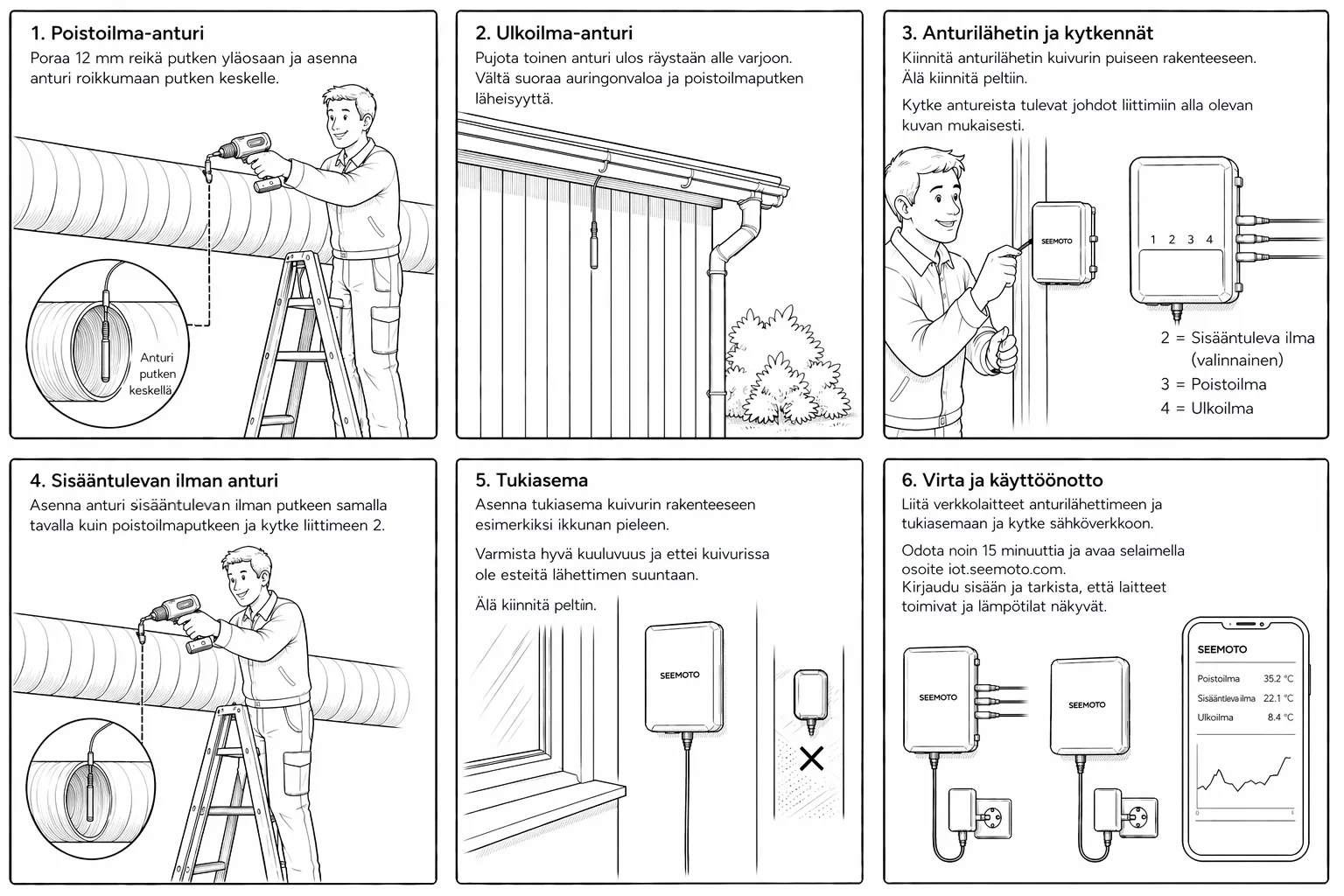
Kuivurivahti installation overview diagram
An overview of every part of the Kuivurivahti system and where it goes: exhaust-pipe sensor, outdoor sensor, sensor transmitter, and gateway. The next images walk through the actual installation, step by step.
Step 2
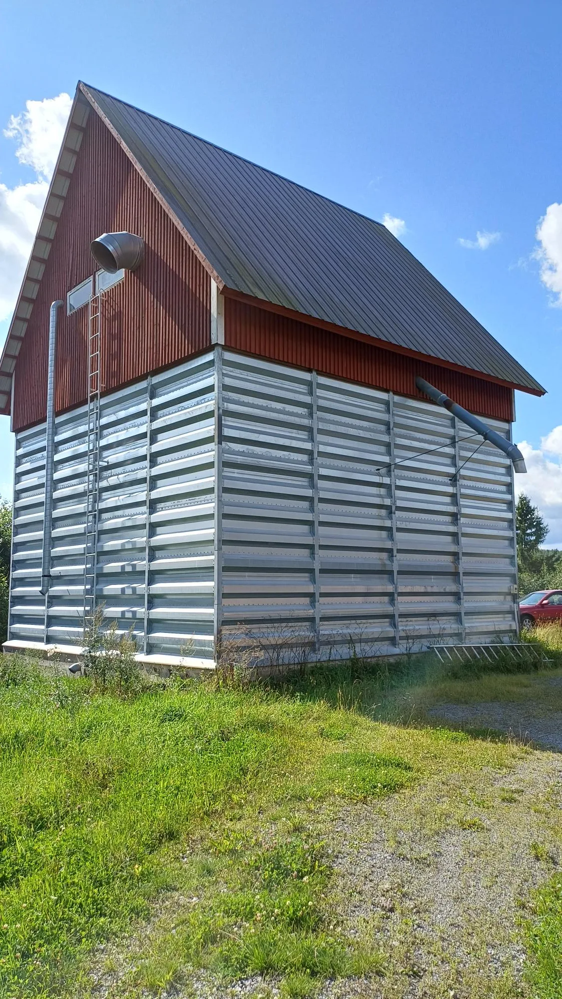
Grain dryer from the side
Side profile of the dryer. It has been in use for decades and now received remote monitoring without any structural retrofit.
Step 3
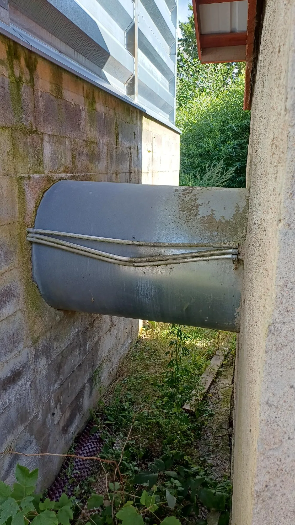
Heated air flowing into the dryer
Heated air moves from the boiler room into the dryer to dry the grain.
Step 4
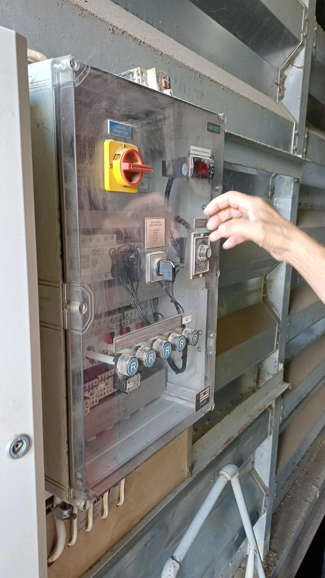
Dryer control panel
The dryer's original control panel. Kuivurivahti does not replace this — it monitors temperatures independently alongside it.
Step 5
Bottom of the exhaust pipe with the dryer's own thermal sensor visible
Bottom end of the exhaust pipe inside the dryer. The black dot is the dryer's own thermal sensor — Kuivurivahti's sensor hangs in the same airflow further up.
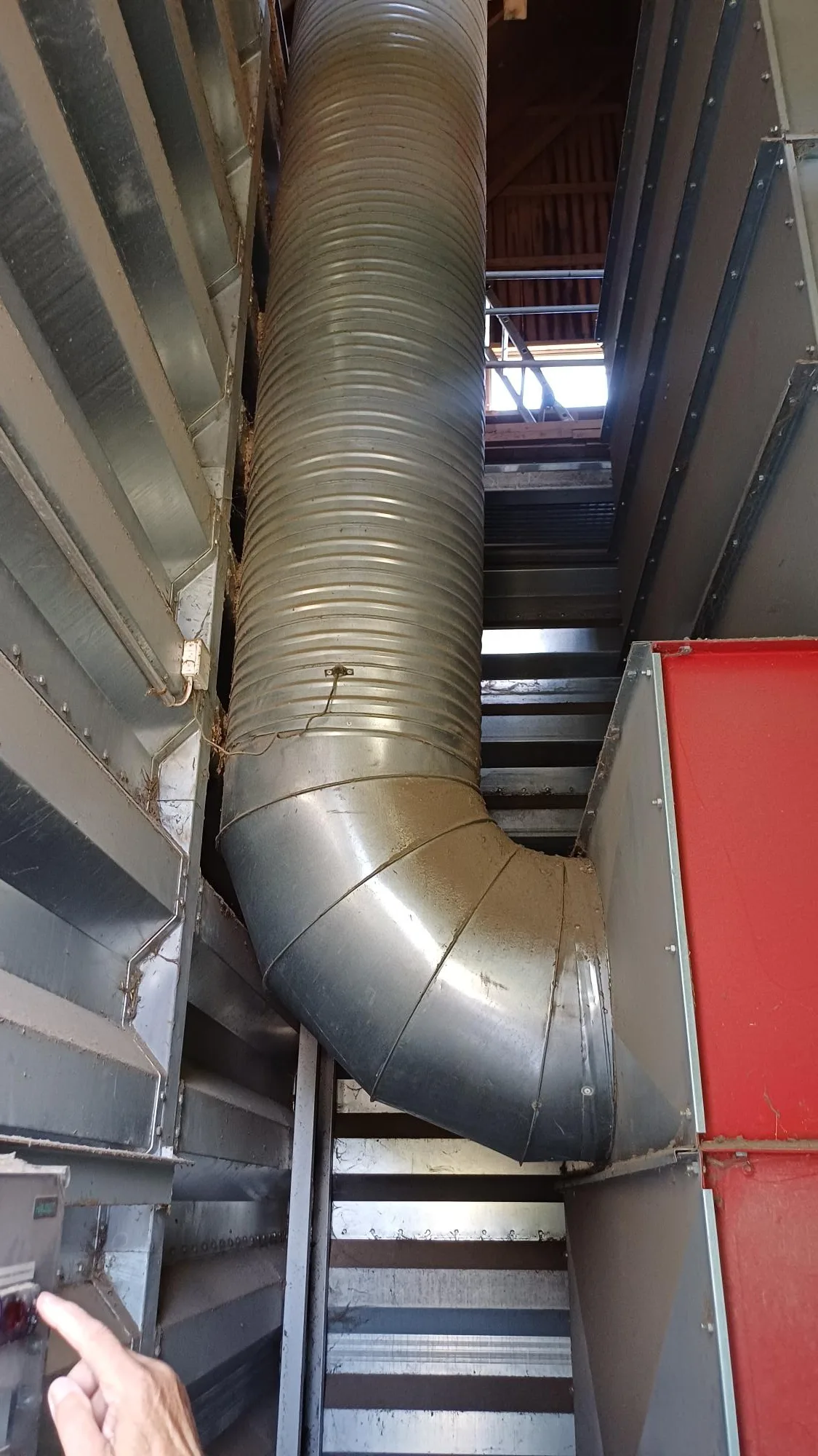
Step 6
Exhaust pipe rising to the upper floor
The exhaust pipe rises from the dryer to the upper floor. The sensor mounting point is chosen at a steady-airflow section.
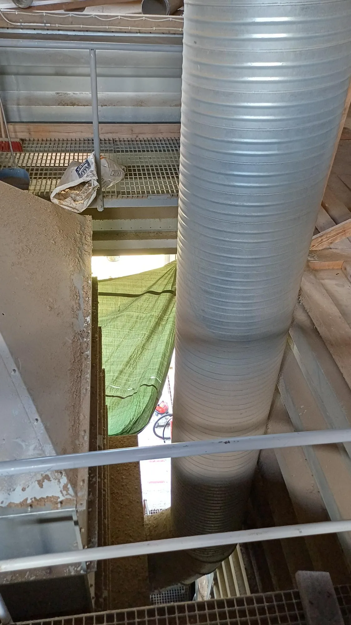
Step 7
Exhaust pipe on the upper floor
The exhaust pipe on the upper floor, before branching towards the outdoor exit.
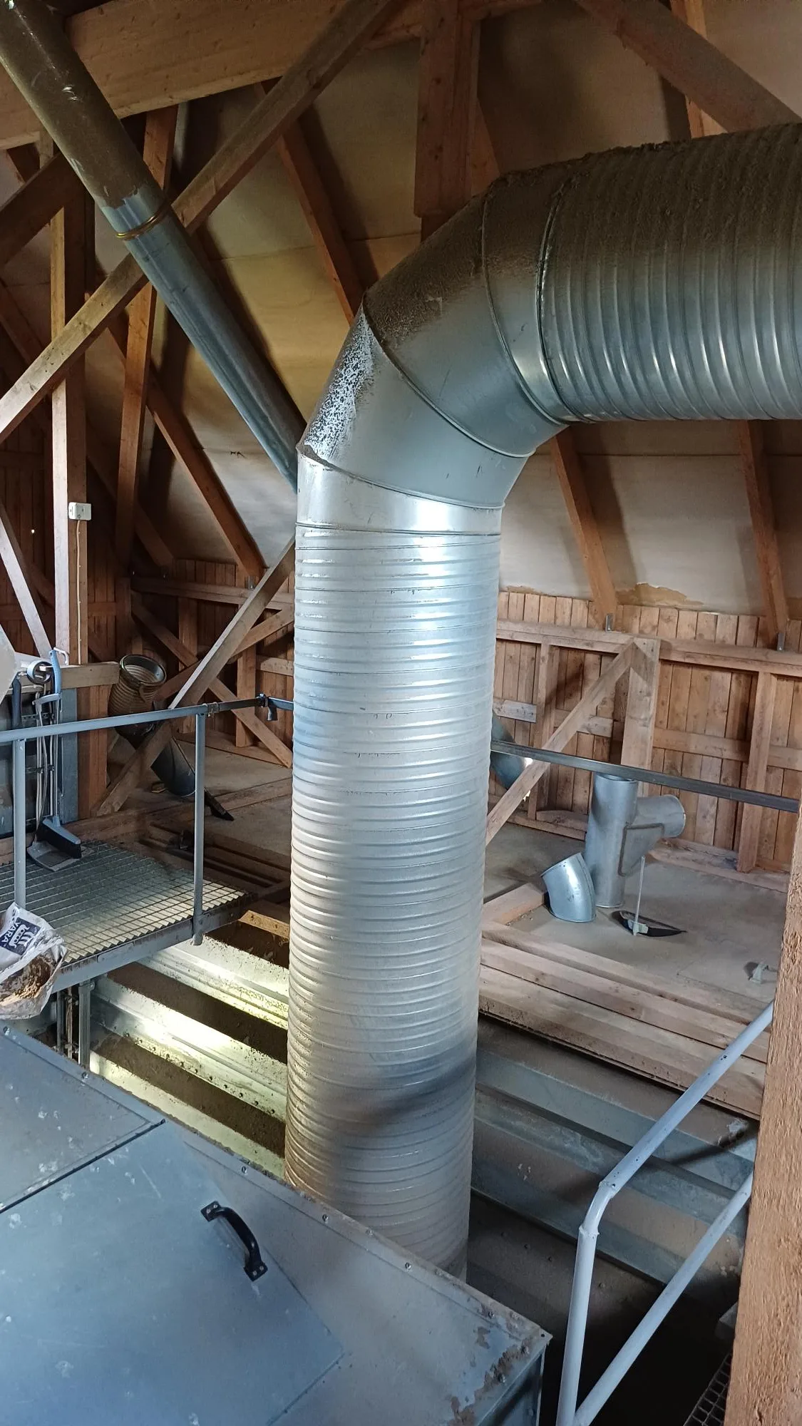
Step 8
Exhaust pipe leaves the building — sensor mounting point
The exhaust pipe continues outside. The sensor sits inside the building, just before the air is pushed out.
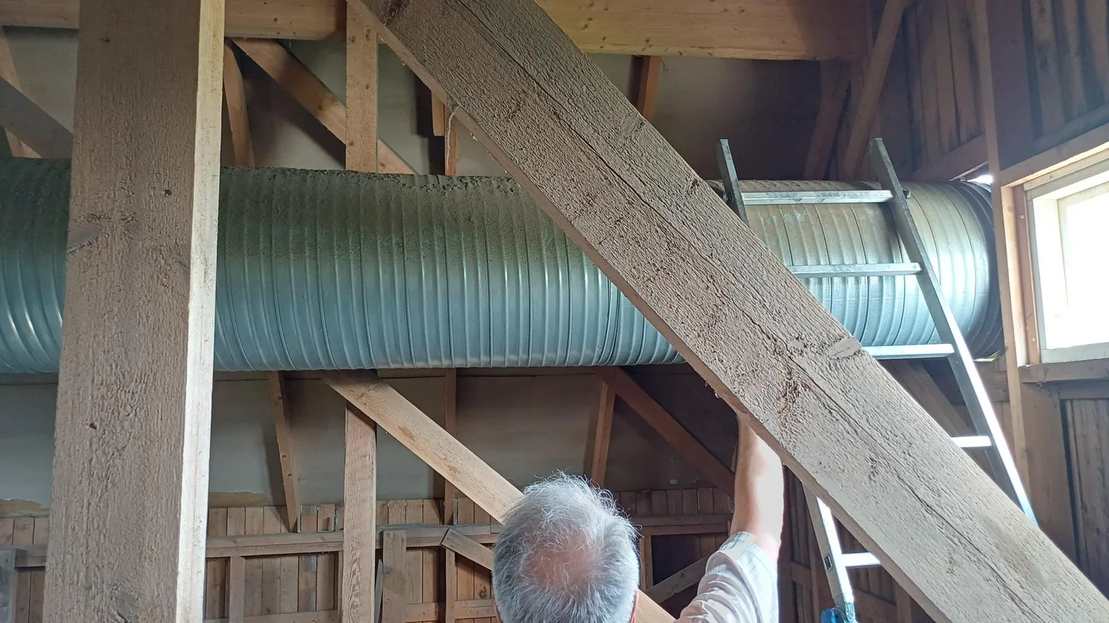
Step 9
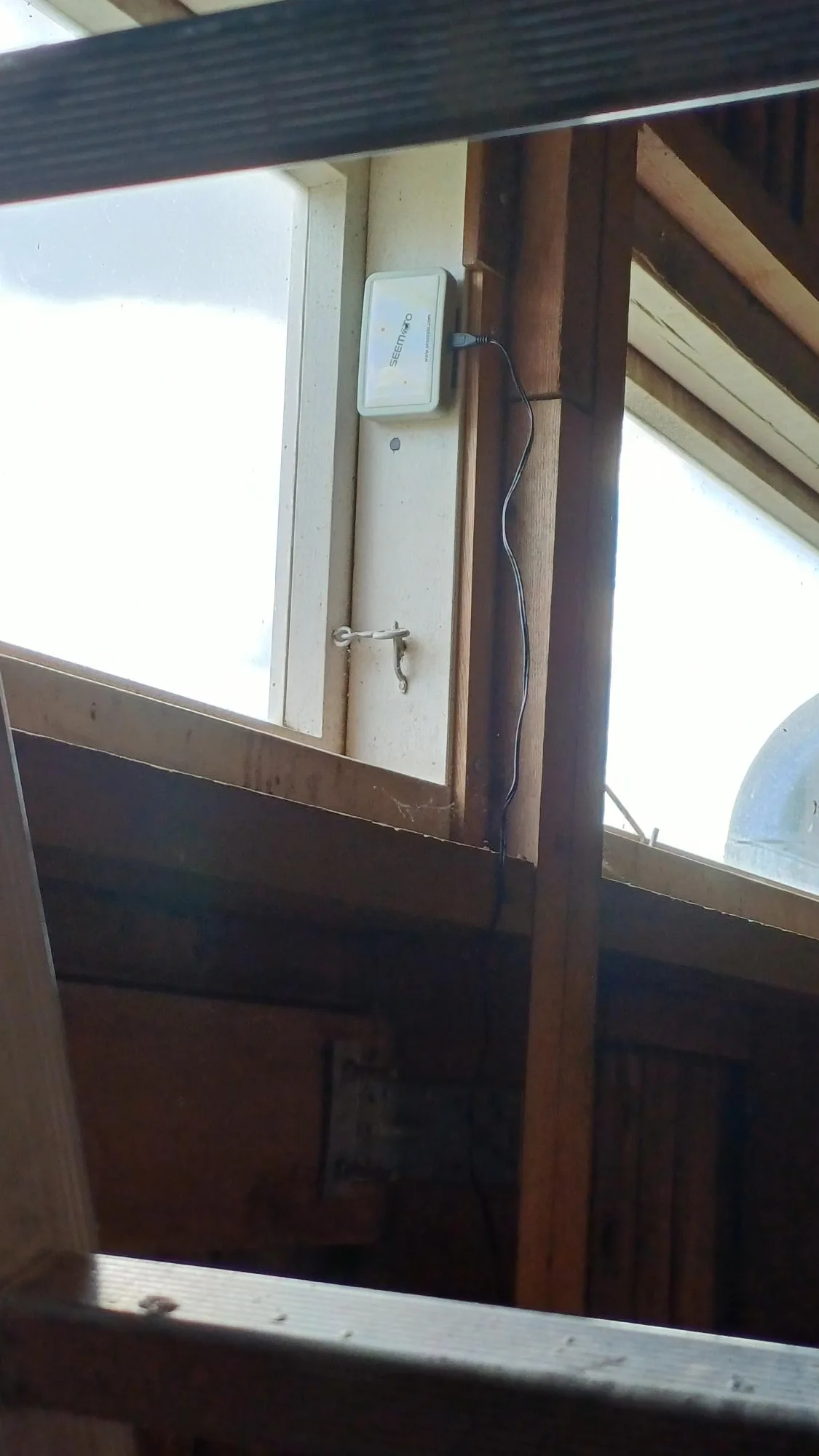
Kuivurivahti gateway installation
The gateway is installed on the dryer wall. It collects data from every sensor and forwards it to the cloud service.
Step 10
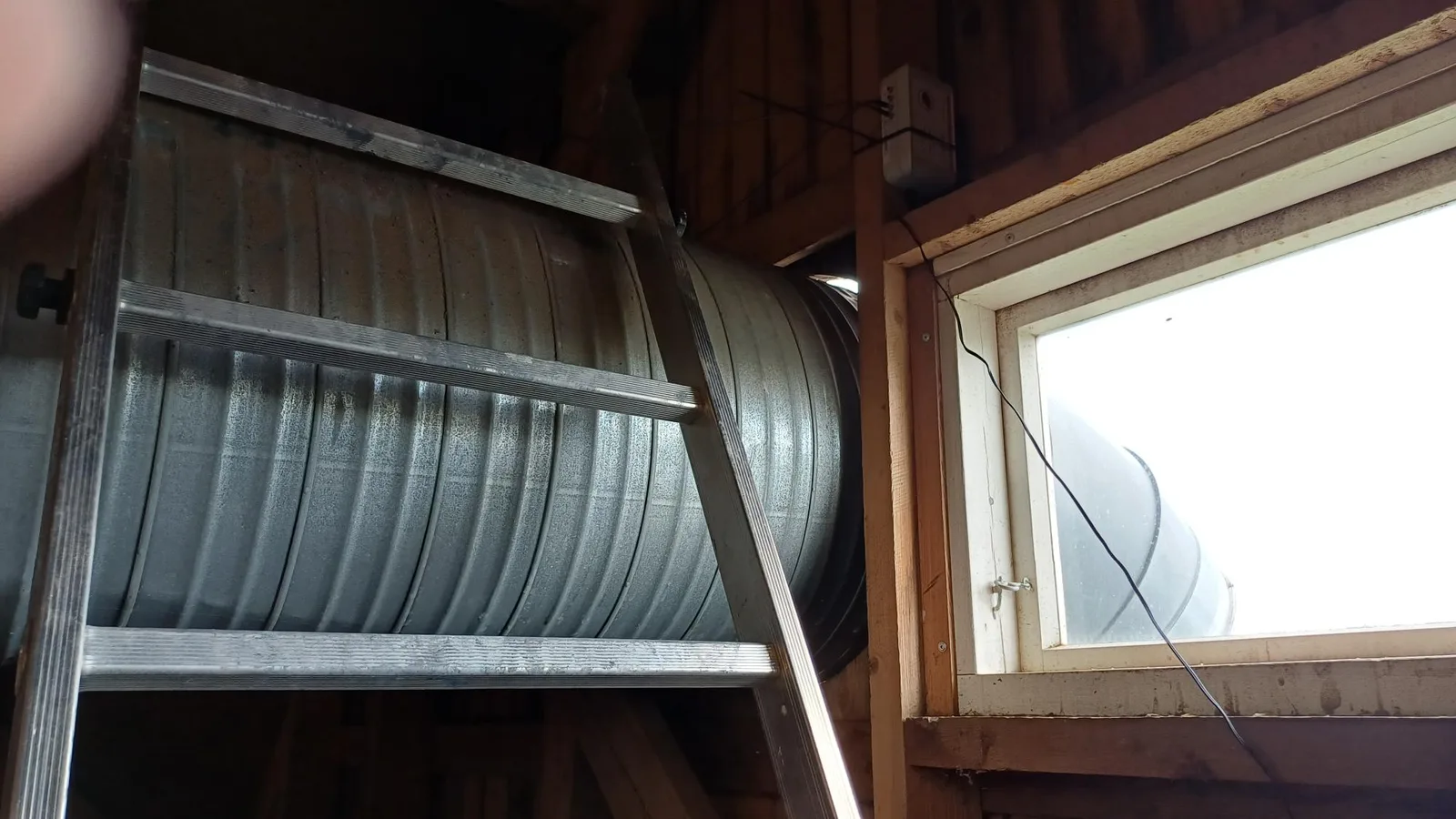
Sensor mounting point on top of the exhaust pipe
The sensor mounts on the upper section of the exhaust pipe, where the temperature most accurately reflects drying progress.
Step 11
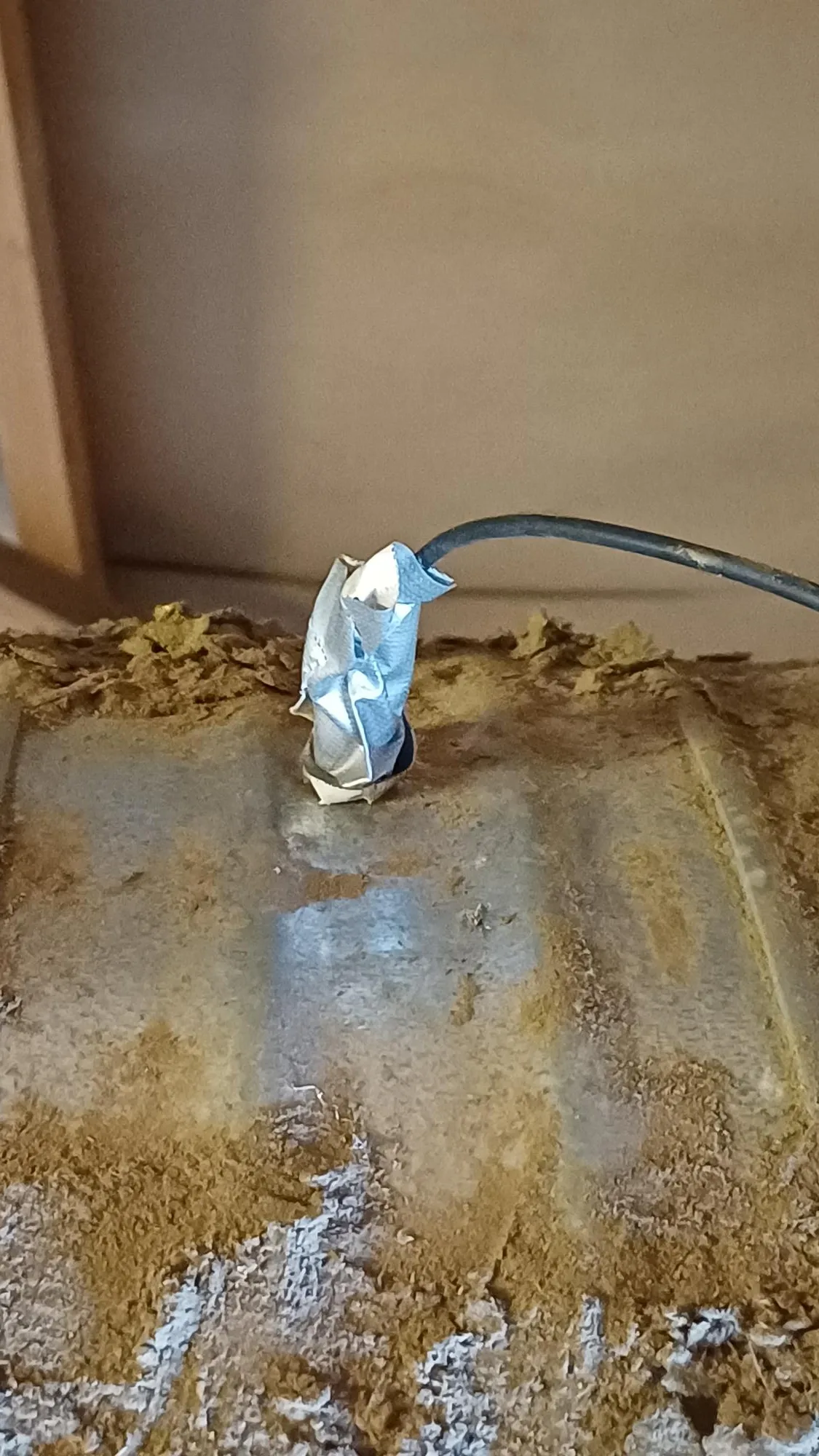
Sensor hanging inside the exhaust pipe
The sensor is suspended inside the exhaust pipe. It measures the temperature and humidity of the air leaving the dryer.
Step 12
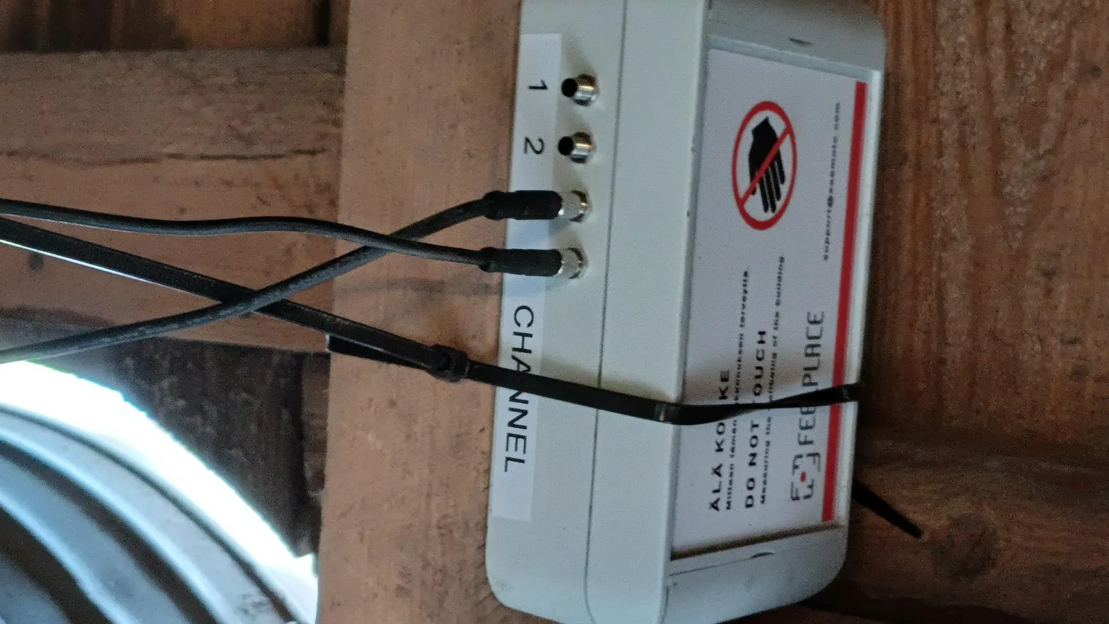
HVACS sensor transmitter installed
In this dryer the sensor transmitter was installed about 1.5 m from the gateway. Sensor cables run easily from the transmitter to the exhaust-pipe measurement point (about 1 m away) and through the wall. The outdoor sensor under the eaves got a 5 m extension cable, so the total cable length is about 6.5 m.
Step 13
Outdoor sensor mounting location
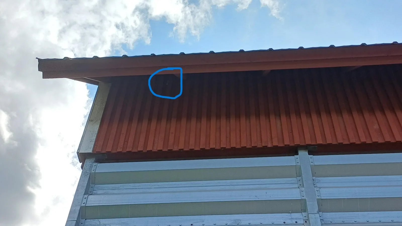
The outdoor sensor needs shelter from sun and rain. Under an eave, in a shaded spot, is a good location.
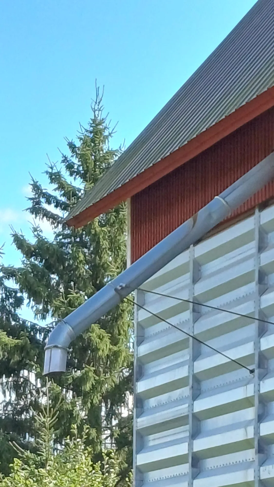
Step 14
Outdoor sensor mounted under an eave, in shade and shelter
Outdoor sensor installed under the eave.
See the photographs larger
Each step has its own page in the photo gallery, where the image is shown full size.
See all installation photos →